Images presented here may not fully represent the product

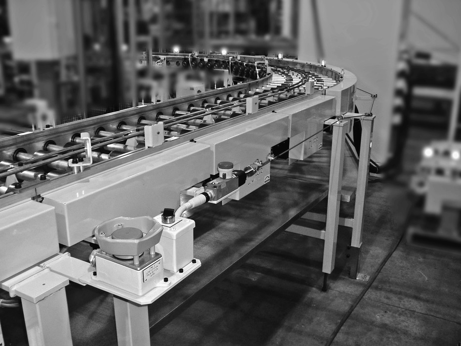
Rope pull switches RPS are emergency stop devices for protecting large, expansive machine or installation areas that cannot be protected by an enclosing housing or cover. Areas of an installation or machine can be shut down immediately from any point in the working area in the event of danger.
Rope pull switches RPS are emergency stop devices for protecting large, expansive machine or installation areas that cannot be protected by an enclosing housing or cover. Areas of an installation or machine can be shut down immediately from any point in the working area in the event of danger.
Task of rope pull switches
The trip range is much larger than for switches with an EMERGENCY STOP pushbutton, since operation is possible over the whole rope length and is not restricted to the small area within reach of the switch. Rope pull switches are used whenever it is necessary to protect large danger areas where it is not possible or too complex to fit a housing or cover.
The advantage is that areas of an installation or machine can be shut down immediately from any point in the working area in the event of danger in cases where it would otherwise be necessary to install individual latched EMERGENCY STOP buttons at short distances apart.
Function and technology used in rope pull switches
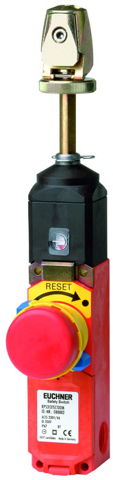
The standard EN 60947-5-5 – 6 (requirements for EMERGENCY STOP pushbuttons and rope pull switches) specifies certain requirements which must be met by rope pull switches and which therefore also define the mode of operation of such switches. As such the latching device (EMERGENCY STOP switch) must be reset by turning a key, by turning the pushbutton in the stated direction or by pulling. Rope pull switches are normally tripped by pulling a plastic-sheathed steel rope (known as the safety rope or pull rope). In addition, EUCHNER rope pull switches feature a latched EMERGENCY STOP button on the housing which has the same effect. Upon tripping, the safety contacts are actuated and a stop signal is generated which switches off the machine. The vertical tensile force which acts on the wire or rope to generate the EMERGENCY STOP signal (contact opening) must be less than 200 N and the vertical deflection of the wire or rope which is necessary for generation of the EMERGENCY STOP signal must be less than 400 mm. An EMERGENCY STOP signal must also be generated if the wire or rope breaks or becomes detached. This means that any fault in the safety device is noticed immediately and the safety function is not lost at any time.
In order to achieve this, the rope pull switch has one center position and two switch-off positions. The switch is in center position during machine operation. If the safety rope is pulled or breaks, the switch moves from the center position to one of the switch-off positions and the machine is stopped. Rope pull switches from EUCHNER have a window which allows the switch position to be seen.
Installation and rope attachment
Installation
In accordance with EN 418 – 4.4, EMERGENCY STOP pushbuttons must be installed so that they can be reached easily and operated safely by persons who are at risk. It may be useful to attach marking flags to improve visibility if wires/wire ropes or ropes are used, as is the case with rope pull switches. A tensioner spring must be installed on the thrust bearing in order to ensure proper and safety-compliant implementation of the pull rope system. This is a precondition for direction-independent tripping at any point along the rope length.
Rope attachment
Versions RPS...SC and RPS...PC
Strip the pull rope and insert into the clamping head. In order to prevent the pull rope from slipping, there must be no rope coating in the clamping head.
Set the pull rope roughly so that the lock marking is in central position and clamp the pull rope firmly with the hexagon socket head screw.
Actuate the pull rope hard several times in order to stretch the rope and then reset the rope using the clamping head.
Set the lock marking in central position by turning the actuation axis.
Activate the rope pull switch by turning the Reset knob in the direction of the arrow (RPS...SC) or by pulling (RPS...PC).
The direction of the safety rope can be changed using rope pulley blocks or eyebolts. Direction changes of up to max. 90° are possible. Rope pulley blocks have the advantage that the frictional forces between the safety rope and deflection points are kept low.
Rope length and temperature dependence
When planning safety installations with rope pull switches, it is necessary to take into account the temperature dependence of the installation and the safety rope so that the switch is not tripped as a result of a change in temperature. To do this, the possible rope lengths must be determined and the trip point must be readjusted regularly. The following graph shows the relationship between rope length and temperature. Installation should take place at a temperature of 20 °C.
Address:
Eltron L.L.L.P.
ul. Brodzka 10B
54-103 Wrocław
Customer Service:
Telefon: +48 71 343 97 55
E-mail: kontakt@eltron.pl
Find us elsewhere: