Images presented here may not fully represent the product

The EUCHNER safety system CMS is based on the magnetic principle. The tamper-proof coded system was specifically developed to monitor moving machine components and movable safety guards.
Magnetically coded safety switches are interlocking devices which are designed to protect people and machines. Compared with electromechanical safety switches, they are used if:
The EUCHNER safety system CMS is based on the magnetic principle. The tamper-proof coded system was specifically developed to monitor moving machine components and movable safety guards.
Functional description
The Coded Magnetic Safety systems CMS comprise three components:
Several permanent magnets are arranged in the actuator housing. The number of magnets, their position (polarization) in the housing and the magnetic field strength characterize the actuator type. For this reason they are also called coded actuators.
Within a series, the individual actuator coding is identical. Using one actuator type on a machine or complete system allows for quick and easy replacement.
Reed contacts are installed in the read head of the safety system CMS. The operating principle for the reed contacts (NC contacts or NO contacts), the number of reed contacts fitted and their physical arrangement determine the type of read head. The contacts blades on the reed contacts will close when under the influence of the magnetic field from the actuator.
The actuators and read heads are matched in pairs and are available in 4 different housings. Depending on the application, the system operator can select a cube-shaped or cylindrical design. The read head only responds to the specific mating component, that is a specific actuator which is allocated to the read head type. The same applies to the allocation of the read head to the evaluation unit.
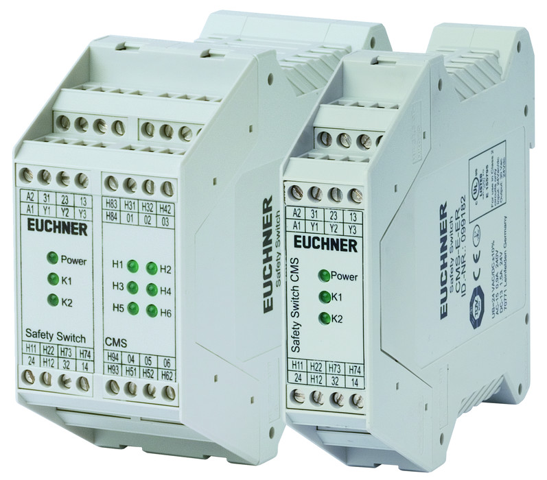
The evaluation unit is the system unit downstream from the read head. Using internal relays, it switches the safety circuit as a function of the position of the reed contacts. The evaluation unit in degree of protection IP 20 is mounted in the control cabinet.
EUCHNER offers various evaluation units. The unit is selected as a function of the number of read heads to be connected and the overall system category to be achieved according to EN 954-1. The related evaluation units are described in detail in the following product sections.
In order to achieve a particular safety level, fault analyses must be carried out where safety-related components are used. A fault could be caused by a short circuit in the connecting lead or by welding of a reed contact in the closed position. If a reed contact is welded, the magnetic force might not be strong enough to open the contact. For reasons of safety, several reed contacts (2 or 3, depending on the switch type) are fitted to each read head.
The NC contact/NO contact combination is used as an example. If the actuator is moved into the read head's operating distance, the reed contacts are switched by the magnets (in the actuator). Magnets with different polarization are assigned to the NC and NO contacts. The downstream evaluation unit monitors the read head: the NC/NO contacts in the read head must always have opposite states. If this is not the case, the safety contacts on the evaluation unit are not switched and the unit switches to the blocked state.
The read head is fastened to the fixed part of the safety guard and is connected to the evaluation unit using a two-core or four-core cable. When the safety guard is closed, the actuator is moved towards the read head. As soon as there is an actuator in the operating distance (i.e. the switch-on distance sao is reached) the reed contacts in the read head switch, i.e. they change their contact position.
If the evaluation unit detects that the reed contacts are in a specific position on all read heads connected, i.e. all actuators are in the operating distance, the safety contact is switched on. If the actuator is moved away from the read head, the magnetic field around the reed contacts reduces with increasing distance. When the switch-off distance sar is reached, the reed contacts return to their pre-loaded position (home position).
The sensitivity of the reed contacts and the field strength of the magnets determine the switching distance between the actuator and the read head. Diagrams of the typical operating distances of the individual sensor units are shown in the technical data for the actuators and read heads. The illustration of the operating distance in x, y and z directions provides the user with information on how the actuator and read head must be positioned. When ideally positioned, the read head is in the middle of the operating distance.
The actuator and read head sensor units have a large operating distance. The advantage of this fact is that the door clearance setting may vary within the limits of the operating distance. The safety systems CMS have switching characteristics with hysteresis (sar > sao).
If the read head is adjusted just inside the actuator's sao operating distance, the plant will not be switched off immediately if the door vibrates slightly. The switch-on and switch-off distances shown in the ordering tables refer to the approach of the sensor unit in the x direction (frontal approach direction). If the actuator approaches the read head from the side, the switching distances are likely to be reduced. The switch-on and switch-off distances in the x, y and z directions are given by the operating diagrams.
An excessively low approach speed in the z direction (side approach direction) can result in an error in the evaluation unit. For further information on the approach speed, refer to the individual product descriptions. The magnetic systems are notable for their high degree of protection and compact design.
They are therefore particularly suitable for areas where dirt and cleaning are major factors.
A major advantage of EUCHNER's safety systems CMS is that the actuator and read head can be fitted behind stainless steel. This property makes it possible to use the system in the food industry in particular. The switching distances are, however, reduced in line with the material and wall thickness. Installation using the corrosion-resistant safety screws (supplied) provides tamper-proof mounting of the actuator and read head on the safety guard.
Address:
Eltron L.L.L.P.
ul. Brodzka 10B
54-103 Wrocław
Customer Service:
Telefon: +48 71 343 97 55
E-mail: kontakt@eltron.pl
Find us elsewhere: