Images presented here may not fully represent the product
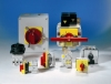
Wyłączniki główne Elektra
Main, emergency off and repair switches
A manually operated main switch must be provided for each mains feed in order to disconnect the machine's electrical equipment from the mains (e.g. when work on the electrical equipment is to be done).
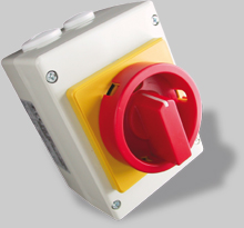
D series main / emergency off switches
At every control point and workplace where an emergency-off function is required, such devices must be present. They must mechanically snap into place automatically and be positioned where they can be easily reached.
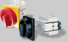
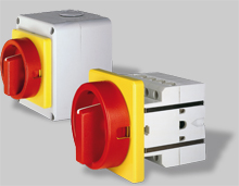
DL series main / emergency off switches
DL switches fulfil the circuit-breaking conditions as per EN for 1000V.
The terminals have individual terminal clamp covers for cable lug and power bus connection on the mains input side. The DHV twin-lever handle has a locking mechanism for 4 padlocks.
The switches can also be supplied in 4-pole format with switchable neutral conductor and an auxiliary switch.
DL series cam circuit breakers fulfil the requirements made by DIN EN 60204 Part 1, clause 5.3 of manually operated main switches. It stipulates that a circuit breaker compliant with EN 60947-3 must be designed for category of use AC-23B.
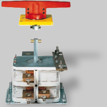
S series main / emergency-off switch with low-voltage circuit breaker
Elektra S series main switches with a low voltage circuit breaker provide protection against automatic restarting when power is restored following a power cut. They fulfil the requirements of DIN EN 60204 Part 1, clause 7.5 by means of a low-voltage circuit breaker coil, which has a mechanism that after any power cut causes the switch to jump back into the 0 position. If there is no power, the switch cannot be turned on.
Additional equipment
Address:
ELTRON Spółka z ograniczoną
odpowiedzialnością Sp. k.
ul. Brodzka 10B
54-103 Wrocław
Customer Service:
Telefon: +48 71 343 97 55
E-mail: kontakt@eltron.pl
Find us elsewhere: