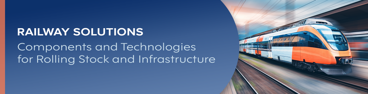
Railway solutions use familiar component types – pushbuttons, fuses, connectors, enclosures – in versions built for operation in a rail vehicle or at the trackside. Their industrial equivalents can perform the same function, but they do not always meet the requirements for vibration and shock, temperature range, fire performance, or the documentation an approval process requires. Some railway products have no industrial equivalent at all, such as pantograph carbon strips, third-rail current collectors, and axle return-current assemblies.
In rolling stock, component requirements depend mainly on their installation location. The standard EN 50155:2017 defines ambient temperature classes; the default class for equipment installed in technical cabinets on board is OT3, covering a temperature range from −25°C to +70°C. The same standard requires continuous operation between 0.7 and 1.25 times nominal supply voltage. Railway infrastructure is subject to other standards, including EN 50122-1 and EN 50122-2. At the same time, components must operate outdoors for years, exposed to condensation, solar gain, and lightning surges.
Neither set qualifies a component for railway use in general – railway solutions are specified by position in the vehicle or on the site rather than by product category.
What Determines Component Selection for Railway Applications?
Component selection in railway applications is determined primarily by where the component is installed, the environmental loads at that location, and the standards that apply to it. Electrical parameters, service life, and long-term availability narrow the choice further.
Location determines environmental requirements because a vehicle or trackside installation can contain several environmental zones. Fire performance can exclude a component that meets every electrical requirement but uses an unsuitable housing material. Long-term availability affects selection because rolling stock and infrastructure remain in service for decades, while a component may become obsolete much sooner.
Which Parameters Follow from the Mounting Position?
Mounting position determines four key selection parameters: the operating temperature class, the shock and vibration category, the ingress protection rating, and the material requirements. The electrical rating is largely independent of mounting position, but it rarely identifies a suitable component on its own.
The range of installation environments is broad: cab, saloon interior, equipment cubicle, underframe, and vehicle roof in rolling stock; trackside cabinet, tunnel, station structure, or technical building in infrastructure. A component correctly specified for one mounting zone may therefore be unsuitable in an adjacent one.
| Criterion | Rolling Stock | Infrastructure |
|---|---|---|
| Dominant load | Vibration and shock | Outdoor environmental exposure |
| Temperature range | Set by mounting zone and the OT class | Set by climate, enclosure, and solar gain |
| Flammability | Assessed to rail fire safety requirements | Site-dependent; more stringent in tunnels and enclosed spaces |
| EMC | Vehicle-level, close to traction equipment | Signalling and fixed installation requirements |
| Service access | Depot-based, planned | Site-based, often remote and costly |
| Service life | Decades, tied to vehicle overhaul cycles | Tied to the lifecycle of the infrastructure asset |
For both rolling stock and infrastructure, the selection process must address what happens if the part is discontinued. Resolving that question at the design stage can avoid later redesign, requalification, documentation changes, and retrofit work.
Which Standards and Technical Requirements Apply to Railway Applications?
The applicable standards for railway applications depend on whether the component is used on rolling stock or railway infrastructure, as well as on its mounting position and operating environment.
| Standard | What it covers |
|---|---|
| EN 50155 | Electronic equipment used on rolling stock |
| EN 45545 series | Fire protection requirements for railway vehicles |
| EN 61373 | Shock and vibration testing of railway equipment |
| EN 50121 series | Electromagnetic compatibility (EMC) in railway applications |
| EN 50122 series | Electrical safety, earthing and return circuits in fixed railway installations |
| EN 50123 series | DC switchgear for fixed traction installations |
| EN 50124 series | Insulation coordination: clearances and creepage distances |
| EN 50125-1 | Environmental conditions for rolling stock and on-board equipment |
| EN 50126 series | RAMS and lifecycle requirements for railway systems |
| EN 50343 | Rules for the installation of cabling on rolling stock |
| EN 50463 | Energy measurement on board trains |
The standard alone doesn’t define the final requirement. The applicable class, test level, or performance criterion depends on the component’s mounting position, operating environment, and role in the railway system.
How to Design the Operator Interface in Railway Applications?
To design the operator interface in railway applications, start by identifying who will use it. A driver, passenger, and technician operating infrastructure equipment all need clear control, confirmation that an action has been registered, and an unambiguous indication of state, while each user group differs in training, attention, and intent.
The control itself is rarely the main problem. Feedback, state indication, and durability are just as important – a failed pushbutton on a driver’s desk can take a vehicle out of service. You should therefore specify railway HMI components for durability and clarity rather than appearance.
How to Select Control and Indication Elements for Railway Applications?
When selecting control and indication elements for railway applications, evaluate switching life, actuation feedback, legibility under changing light, and ingress protection. You should also check resistance to cleaning agents, especially for components exposed to frequent maintenance.
A driver’s desk is operated repeatedly throughout the working day and across the service life of the vehicle. Feedback matters because the driver may register an action haptically or in peripheral vision rather than by looking directly at the control. Illuminated pushbuttons such as EAO’s railway ranges can provide both action confirmation and clear state indication. Sensata components also work in the desk, including position sensors and panel-mounted circuit breakers.
How Do Requirements Differ for HMI Elements Accessible to Passengers?
For passenger-accessible HMI, account for untrained users, frequent operation, and the risk of deliberate damage. These elements also often form part of a monitored door or alarm circuit rather than acting as simple standalone switches.
Passenger-accessible HMI elements have to hold up mechanically and electrically alike, so consider IP and IK ratings alongside switching endurance. TSI PRM requirements shape the design of door release and passenger-accessible controls, including their tactile identification, visual contrast, and accessibility.
What Electrical Connections Are Used in Railway Applications?
Railway installations use connectors, terminal blocks, connection blocks, wired connections, and circuit marking systems in both vehicle and infrastructure control cubicles.
For these connections, you need to consider two requirements together: mechanical retention and contact integrity. Mechanical retention keeps the connection secure under vibration and shock, while contact integrity keeps resistance at the interface low and stable. If contact pressure falls, resistance and local heating can increase, accelerating further degradation.
What Affects Connection Durability in Railway Conditions?
Connection durability in railway conditions is shaped by six main factors:
- Vibration resistance – helps maintain sufficient contact pressure regardless of the installation torque.
- Contact quality – keeps interface resistance low and stable.
- Mechanical strength – allows the connection to withstand shock loads and handling during maintenance.
- Corrosion resistance – protects against condensation, airborne salt, and outdoor contamination.
- Ease of servicing – reduces the time needed to disconnect and reconnect the connection.
- Error prevention – helps avoid mismating and keeps circuit identification clear and unambiguous.
Screw terminations depend on correct installation torque, while spring technologies such as push-in and push-x maintain contact force independently of it, which is why ranges built for railway duty, such as Phoenix Contact’s, are usually preferred where vibration is significant. Cabling installation on rolling stock is governed by EN 50343.
Terminal Blocks and Potential Distribution in Railway Installations
Terminal blocks distribute potentials across circuits and organise wiring for faster fault finding. During maintenance, clear circuit separation and identification are often as important as the electrical function itself.
Dedicated blocks for supply and return potentials let a technician isolate individual sections without disturbing the surrounding wiring. Marking that matches the documentation helps verify the circuit before anything is disconnected – diagnosis and servicing become faster and more predictable.
How to Protect Electrical Installations in Railway Applications?
To protect a railway electrical installation, address short circuits, overloads, and overvoltages – plus damage to cables and connected devices. You cannot assume that protective devices selected for a standard industrial installation will be suitable for railway use.
DC operation is the main difference – protective devices must interrupt DC fault current without the help of a natural current zero crossing. In both rolling stock and infrastructure, selectivity matters: the protection should isolate the faulty circuit while keeping the rest of the system operating.
Power circuits in substations and on vehicles use apparatus designed for direct current: Joslyn Clark DC contactors, Joslyn Clark vacuum apparatus up to 12 kV [IEC 60470], and where switching frequency and the absence of moving parts matter, Crydom PowerPlus DC solid-state relays.
How to Select Circuit Protection for Railway Applications?
To select circuit protection for railway applications, first define the protection function required, then evaluate six parameters:
- Rated DC voltage – should match the actual circuit voltage rather than an AC equivalent.
- Rated current – should be selected with the ambient temperature at the installation point taken into account.
- Breaking capacity – must be sufficient for the prospective fault current at that location.
- Time–current characteristic – should protect the load while maintaining selectivity with the rest of the protection system.
- Mounting arrangement – should fit the available space and allow convenient service access.
- Circuit time constant (L/R) – determines DC breaking capacity.
A fuse installed inside a warm, enclosed cubicle may not perform as it does under catalogue reference conditions. For traction applications, you should therefore check the characteristic curve against the actual circuit conditions. Mersen’s high-speed fuse ranges for semiconductor protection are one example where this matters.
Power Distribution and Protection – Rolling Stock and Trackside Equipment
Organise power distribution in a railway installation as a sequence of conversion, circuit distribution, backup for critical loads, and continuity monitoring. Circuit breakers, relays, contactors, and surge protection are coordinated across the installation rather than selected in isolation. Mersen and Phoenix Contact cover different parts of this chain, and coordinating protection with distribution usually means combining components from both within one design.
How to Protect Electronics Against Temperature and Operating Conditions?
To protect railway electronics, treat the enclosure as three protection barriers at once: mechanical, thermal, and electromagnetic. These requirements interact, because sealing against water and dust can also reduce heat dissipation.
Temperature matters in both rolling stock and infrastructure, because sustained operation above the intended range accelerates component ageing and reduces service life. Thermal management should be part of the enclosure specification rather than an add-on.
Enclosure and Cooling as a Single Electronics Protection System
Specify the enclosure and its cooling together, because tighter sealing can reduce passive heat dissipation. Start with a heat balance rather than a cooling device, then use the simplest method that can remove the remaining thermal load.
Available cooling methods include natural convection, conduction cooling, forced ventilation with fans, air-to-liquid heat exchangers, and air conditioners. Trackside enclosures from nVent Schroff may combine environmental protection with thermal management within the same system.
How to Monitor Installation Status and Electrical Parameters in Railway Applications?
Condition monitoring in railway applications tracks voltage, current, circuit loading, and relevant environmental parameters. The value comes from interpreting trends and thresholds rather than from measurement alone:
- A rising current draw can indicate a degrading load.
- Current asymmetry can point to a circuit or load problem.
- Voltage deviation can indicate an auxiliary supply or distribution issue.
- Temperature and humidity trends show how operating conditions are changing.
Carlo Gavazzi, among others, offers relays and control equipment for such applications.
Measurement in a traction circuit starts with isolation. A 3 kV DC voltage is not measured with a controller’s analogue input – between the power circuit and the measuring system sits a transmitter with insulation designed for that voltage, for example the Knick P51000 or P52000, meeting EN 50155, EN 50124-1, IEC 62497-1, EN 61373, and EN 45545-2. Traction energy billing requires a measuring chain compliant with EN 50463 – measuring components are specified together, for example Knick shunt resistors and transducers with a declaration of conformity to EN 50463 and EN 50463-2.
How to Measure Motion and Confirm State in Railway Systems?
Motion in railway systems – speed, distance, and position – is measured with encoders, and the version required depends on the mounting location. On-board encoders operate on the wheelset axle and need declarations to EN 50155 and EN 61373, which Hengstler versions provide. Trackside encoders work in point machines, where resolution and the communication interface matter most, most often SSI or Profinet. Where the position signal feeds a safety function, Sensata/BEI encoders certified to SIL3 and PLe are used.
In signalling circuits, feedback on switching state comes from relays with force-guided contacts. Hengstler relays declared to EN 50205 and UIC 736e are intended for such circuits.
How to Improve Component Reliability Across the Installation’s Entire Lifecycle?
Component reliability across the installation lifecycle is not a property of the product alone – it comes from a chain of decisions:
- Selection – places the component in an environment it can handle.
- Installation – keeps it secure, particularly at electrical connections.
- Temperature control – influences how quickly it ages.
- Protection – limits damage when an upstream fault occurs.
- Monitoring – turns degradation into a planned intervention.
- Serviceability – determines how easily and cost-effectively that intervention can be carried out.
Reliability is therefore a design question rather than a procurement one. A qualified component can still fail early if it operates in excessive heat, uses terminations vulnerable to vibration, or cannot be monitored and serviced effectively.
How to Select Components When Modernising Rolling Stock and Railway Infrastructure?
When you modernise rolling stock or railway infrastructure and a component has been discontinued, you need to select a replacement on three levels: mechanical and mounting fit, electrical and functional compatibility, and compliance with the original approval basis. Component selection for rolling stock modernisation should start from the requirements arising from the approval basis, and you should check that the replacement cites the same standard in its datasheet.
Standardisation can reduce the same problem in future upgrades. Modernisation is therefore a good opportunity to consolidate equivalent functions where the technical and approval requirements allow it.
Select Components for Railway Applications with ELTRON
Most railway component requirements begin with the installation context. Mounting position determines the environmental conditions, relevant standards, and failure modes you need to consider – whether the component sits in a driver’s desk, equipment cubicle, or trackside enclosure. Reliability depends on how these decisions work together.
A railway installation is rarely specified from one catalogue. HMI elements, connections, protection, enclosures, and monitoring devices often come from different specialist manufacturers and still need to work as one system. ELTRON brings these component groups together in one order and one delivery.
Browse the full range of railway solutions or contact our technical team – tell us the application, mounting position, and constraints, and we’ll help narrow the component selection.