Why 100 kA? A combination of an SPD and a gG fuse selected from the datasheet table is typically limited to 25 kA – a threshold already exceeded by the short-circuit current on the LV busbar of a 1250 kVA transformer. That is where the SSD holder replaces the fuse. This article explains where these figures come from, how to compare declarations from different manufacturers, and when the SSD holder beats an NH disconnector. It also covers which version to choose for trackside facilities supplied by overhead lines, where the SSD holder works alongside other railway components.
What Is an SSD Holder?
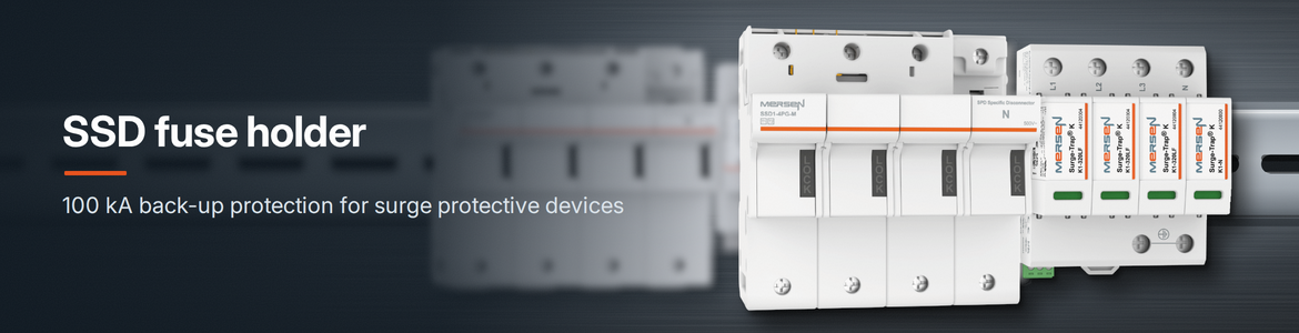
An SSD holder (SPD Specific Disconnector) is a back-up protection device for a surge protective device, which the manufacturer tests together with a specific SPD series and for which the short-circuit withstand rating is declared for that combination. It sits in the SPD branch, where back-up protection is required, in the same position normally occupied by a fuse base with a blade or cylindrical fuse. For the Surge-Trap® K1 series, the combination with the SSD K1 holder achieves a short-circuit withstand rating of 100 kA.
The plug-in element has the dimensions of a 14 × 51 cylindrical fuse. The housing occupies four poles on a TH35 DIN rail and accepts conductors up to 35 mm². The version with a microswitch provides remote status signalling.
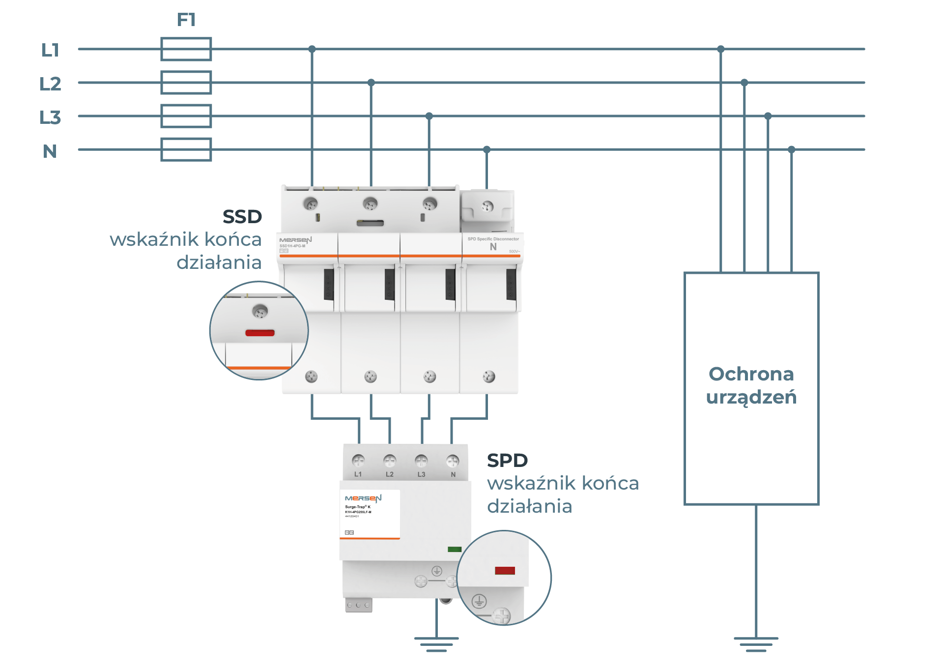
SSD holder in the branch, between the L1, L2, L3, N busbars and the SPD. Each device has its own end-of-life indicator. Manufacturer’s drawing.
Back-up protection is selected to match the number of poles of the SPD, and the manufacturer provides a compatibility table with catalogue numbers. A 3-pole holder can also be used with 4-pole SPDs, provided a separate disconnecting device is installed in the N conductor. The pairs covered by the test are listed in an annex to the system declaration.
The back-up protection also serves a second purpose: a short circuit in the SPD is an earth insulation fault, so the upstream protective device must disconnect the supply within 5 s, as in any distribution circuit. In a TN network the fault loop consists entirely of conductors and the fault current is high. In a TT network the L-PE loop closes through the earth and the current may not reach the operating threshold of the back-up device — hence the 3+1 arrangement in TT (Surge-Trap® K1-4PG): varistors between L and N, spark gap between N and PE; a varistor short circuit then produces an L-N loop through conductors with sufficient current for the SSD holder3. The N-PE spark gap path does not carry follow current and does not require back-up protection.
What Are the Parameters of the SSD K1 Holder?
The SSD K1 holder has two current thresholds, each referring to a different phenomenon. The impulse current Iimp = 12.5 kA (10/350 µs) is the surge the SSD element carries without melting or interrupting the circuit. The operating current Itrip = 500 A is the lowest 50 Hz short-circuit current at which the element interrupts the circuit; below this level the circuit remains under the thermal disconnector of the SPD. No load current flows through this path, so the fuse element is not sized for the load current.
The upper boundary of the current range the SSD element can interrupt is the short-circuit withstand rating Isccr = 100 kA: the largest prospective current at the installation point at which the combination interrupts the circuit without damage. This is a property of the combination — the Surge-Trap® K SPD alone has an Isccr of 25 kA; only together with the SSD holder does the combination reach 100 kA.
For comparison: a gG fuse in the SPD branch melts under a 10/350 µs impulse of 9.3 kA for a 100 A fuse, 12.1 kA for 125 A, and 16.1 kA for 160 A1. A 12.5 kA per-pole impulse therefore destroys a 125 A fuse, while the SSD K1 element carries it without damage.
A fuse operating in the shunt branch disconnects the SPD and the event may go unnoticed — and without the first level of protection, the downstream stages are ineffective2. This is the case for specifying the version with a signalling contact (M) and a status indicator on both devices.
| Parameter | Value |
|---|---|
| Impulse current Iimp (10/350 µs) – lightning impulse carried without operation | 12.5 kA |
| Nominal discharge current In (8/20 µs) – repetitive impulse, carried multiple times | 20 kA |
| Short-circuit withstand rating Isccr – prospective current at which the combination interrupts safely | 100 kA |
| Minimum operating current Itrip – below this value the holder will not interrupt the circuit | 500 A |
| Let-through current – peak current passed to the installation during a short circuit | 17.08 kA per pole |
| Operating voltage Ue – maximum permissible voltage in the holder circuit | 500 V AC |
| Element dimensions | 14 × 51 |
| Rail width | 80 mm (3-pole) / 107 mm (4-pole) |
| Terminals | 1.5 to 35 mm² rigid, 1.5 to 25 mm² stranded |
SSD K1 series data from the manufacturer’s datasheet.
Which Version to Choose: 12.5 kA or 25 kA per Pole?
The choice is determined by the impulse current per pole, since both series share the same 100 kA short-circuit withstand rating. The SSD K1 series is used with Surge-Trap® K1 SPDs rated at 12.5 kA impulse current. For 25 kA SPDs there is a separate SSD K1H series with a 22 × 58 element and an operating current of 1100 A; the 3-pole SSD1H-3P-M holder occupies 105 mm of rail at 35 mm per pole.
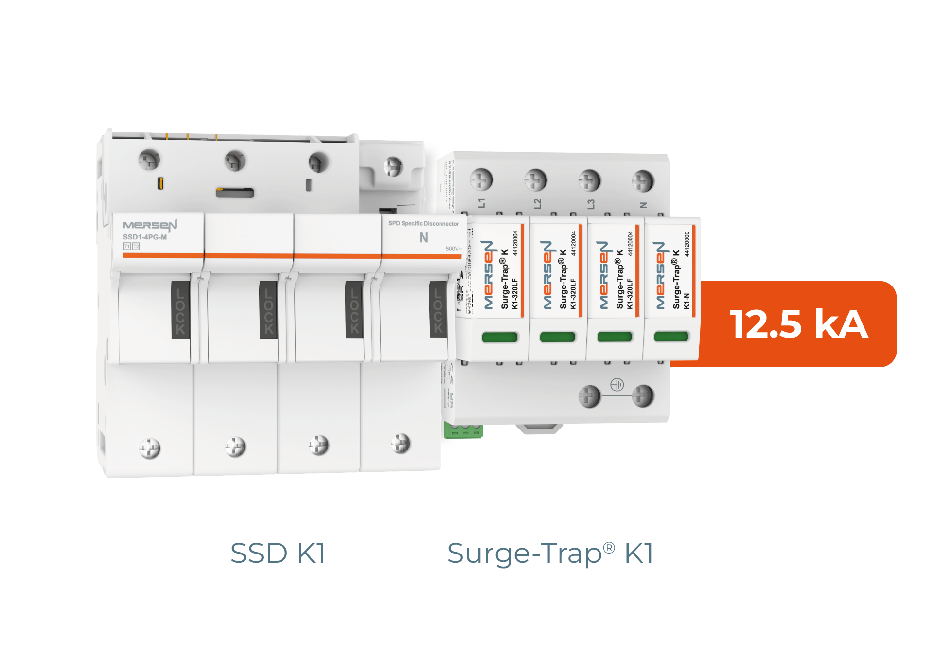
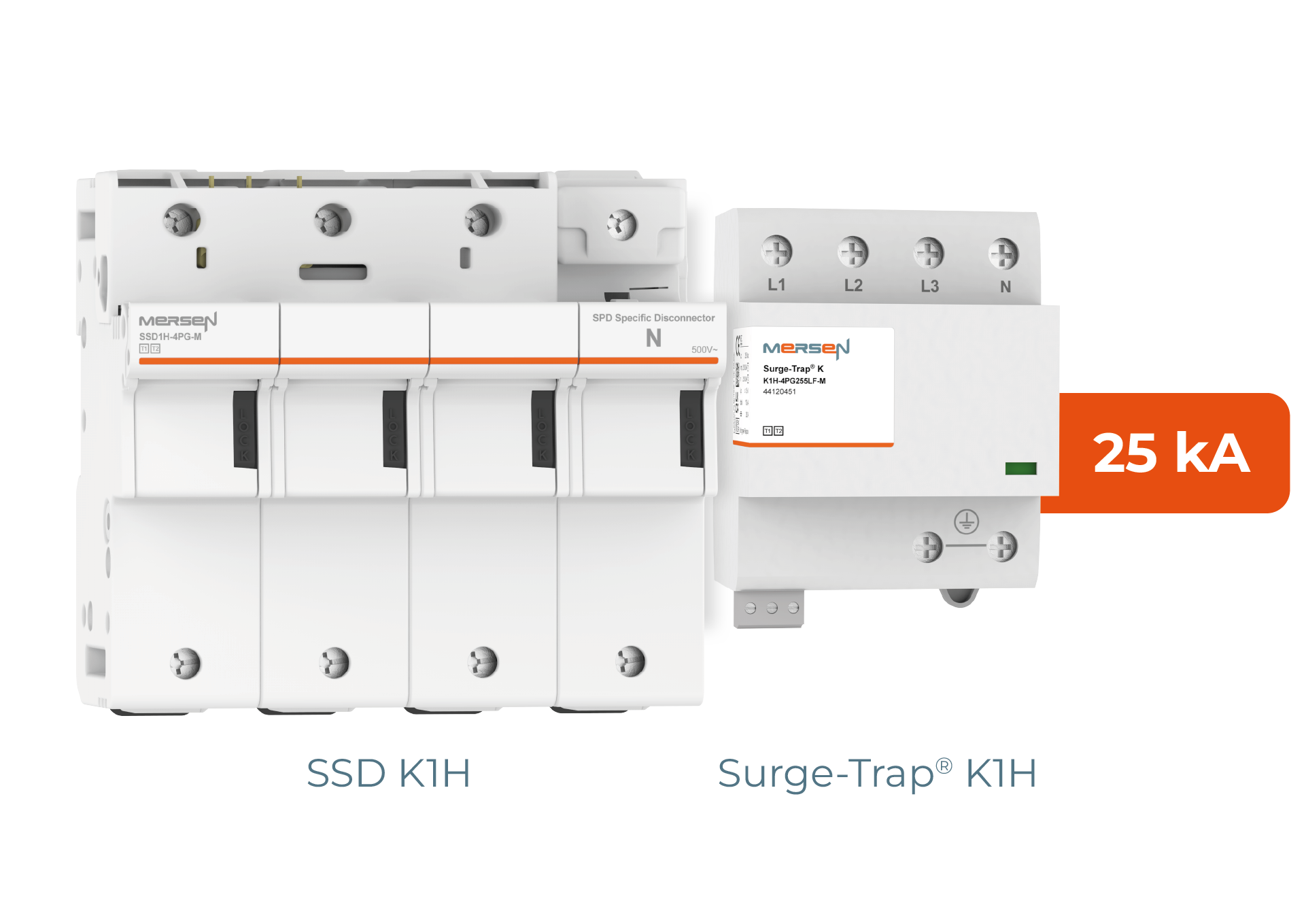
K1 series with SSD K1 holder, 12.5 kA per pole K1H LF series with SSD K1H holder, 25 kA per pole
The boundary between versions is set by the distribution of lightning current. Half the current goes to earth, the remainder is shared among the live conductors, so the share per pole depends on the lightning protection level (LPL) of the installation and the number of conductors. The table below shows this distribution for four conductors.
| Protection level LPL | Lightning current 10/350 µs | Per pole with 4 conductors | Version |
|---|---|---|---|
| LPL I | 200 kA | 25 kA | K1H + SSD K1H |
| LPL II | 150 kA | 18.75 kA | K1H + SSD K1H |
| LPL III and IV | 100 kA | 12.5 kA | K1 + SSD K1 |
I per pole = 0.5 × I(LPL) / n, where n is the number of supply conductors — four for a three-phase connection, also in TN-C networks, because the PEN conductor carries its share of the current through the connection to the equipotential busbar4. Lightning current values for protection levels per IEC 62305-1. The 0.5 factor is a standard assumption; the actual current distribution for a specific installation must be calculated.
The 25 kA version therefore applies where the installation has a lightning protection system of class LPL I or LPL II, and for overhead-line supplies. The K1H has a monobloc construction, so the entire unit is replaced in the event of damage, while the plug-in Surge-Trap® K1 allows the module to be removed from the base separately.
Where Does the 100 kA Requirement Come From?
The 100 kA requirement comes from the fact that the SPD and back-up protection combination must safely withstand and interrupt the maximum prospective short-circuit current at the installation point, for example on the busbars of a transformer substation, without rupturing the housing or projecting an arc externally. The short-circuit withstand rating Isccr defines precisely this current. A varistor at the end of its service life short-circuits, and the back-up protection then interrupts the circuit.
For a spark-gap SPD, the back-up protection has a different physical meaning. After an impulse, ionised gas in the spark gap carries follow current — the short-circuit current of the network at operating voltage, approximately equal to the prospective short-circuit current at the installation point. The arrester must extinguish it at the first current zero; if it exceeds the follow-current extinction capability If (1.5–4 kA for conventional designs, 25–50 kA for current-limiting types), the fuse interrupts it, but the fuse must first withstand the combined Joule integral of the lightning current and the follow current5. A varistor-based SPD does not produce follow current; back-up protection only operates when the varistor short-circuits after thermal runaway — and that is the situation Isccr addresses.
On the LV busbar of a transformer substation, the short-circuit current depends almost entirely on the transformer rating. An SPD combined with a gG fuse selected from the datasheet table is limited to 25 kA, so the transformer rating immediately shows from which point that limit is no longer sufficient. The SSD holder raises the threshold fourfold.
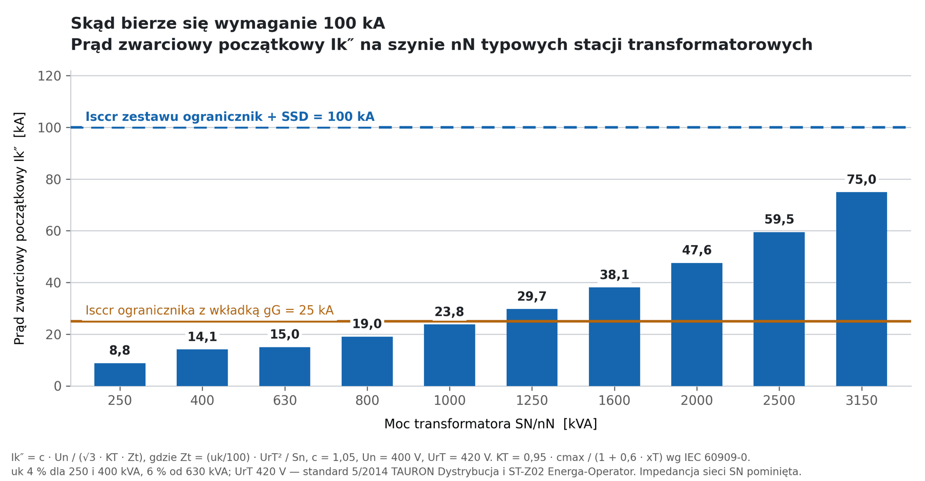
Initial short-circuit current Ik″ on the LV busbar as a function of transformer rating. Own calculations; MV network impedance omitted.
| Transformer | uk | Zt | KT | Ik″ on LV busbar |
|---|---|---|---|---|
| 250 kVA | 4% | 28.22 mΩ | 0.974 | 8.8 kA |
| 400 kVA | 4% | 17.64 mΩ | 0.974 | 14.1 kA |
| 630 kVA | 6% | 16.80 mΩ | 0.963 | 15.0 kA |
| 800 kVA | 6% | 13.23 mΩ | 0.963 | 19.0 kA |
| 1000 kVA | 6% | 10.58 mΩ | 0.963 | 23.8 kA |
| 1250 kVA | 6% | 8.47 mΩ | 0.963 | 29.7 kA |
| 1600 kVA | 6% | 6.62 mΩ | 0.963 | 38.1 kA |
| 2000 kVA | 6% | 5.29 mΩ | 0.963 | 47.6 kA |
| 2500 kVA | 6% | 4.23 mΩ | 0.963 | 59.5 kA |
| 3150 kVA | 6% | 3.36 mΩ | 0.963 | 75.0 kA |
Ik″ = c·Un/(√3·KT·Zt) per IEC 60909-0, where Zt = (uk/100)·UrT²/Sn, c = 1.05. Un = 400 V is the nominal network voltage, UrT = 420 V is the nominal LV winding voltage. KT = 0.95·cmax/(1+0.6·xT) is the network transformer impedance correction factor; once applied, the result no longer depends on cmax. Short-circuit voltage uk: 4 % for 250 and 400 kVA, 6 % from 630 kVA; UrT 420 V and ratios 15.75/0.42 kV and 21.0/0.42 kV per TAURON Distribution Technical Standard 5/2014 and Energa-Operator specification ST-Z02. MV network impedance omitted, so values are an upper estimate: at an MV network fault level of 250 MVA the result would be lower by 4 % at 400 kVA and by 18 % at 3150 kVA.
The transformer rating is an approximation of the short-circuit current; the binding figure remains the prospective current at the point where the SPD will be installed. The further that point is from the substation, the lower the current, because cable impedance adds to the loop.
Up to 1000 kVA the result stays below 25 kA, within the range of the conventional fuse combination; the boundary falls at approximately 1050 kVA. From 1250 kVA upward the busbar current exceeds that threshold, and substations of 2500 and 3150 kVA yield 59.5 and 75.0 kA. A rating of 100 kA covers the full practical range of distribution transformers, including margin for the peak value.
The transformer rating alone does not determine the order. At the boundary between 400 and 630 kVA the short-circuit voltage switches from 4 to 6 %, so a 630 kVA substation yields 15.0 kA against 14.1 kA for 400 kVA: a 57 % increase in rating raises the short-circuit current by only 6 %. Above 3150 kVA manufacturers raise uk to 7–9 % to limit the LV short-circuit current.
How to Read a 100 kA Declaration?
A 100 kA declaration must be read together with the test conditions: what the figure refers to, whether it is an rms or peak value, and at which operating voltage it applies. Several manufacturers now quote 100 kA, backed by different technical approaches: a separate SPD-specific disconnector, an SPD with a fuse built into its housing, or an SPD in an NH fuse body. When comparing offers, what matters is what that figure refers to and under what conditions it was measured.
The same number in two datasheets means different things. In one it refers to the combination of an SPD with a separate back-up device; in another, to a single unit with a fuse built into the housing. Some datasheets also quote the peak value alongside the rms value — more than twice as high. It can also happen that the protective circuit section of the datasheet quotes half that value, and 100 kA appears only in supplementary data, at a lower operating voltage.
Before comparing two products, check five things in the datasheet:
- What the withstand rating refers to: the combination with back-up protection, or the SPD alone.
- Whether the stated value is rms or peak.
- At which operating voltage it applies – a datasheet may quote a higher withstand at a lower voltage.
- What back-up protection the manufacturer assumed: an external fuse from a table, or a built-in element.
- What the operating current of the back-up device is. It sets the lower boundary of the range in which the back-up device operates – currents below that value remain under the SPD’s thermal disconnector.
Observations from a review of manufacturer datasheets, September 2026.
The difference between the withstand rating of the SPD alone and the withstand rating of the combination is visible directly in the DEKRA certificate for the Surge-Trap® K series. It states Isccr of 25 kA and the maximum upstream overcurrent protection device, with EN 61643-11:2012 with amendment A11:2018 as the test basis (when comparing offers, the edition of the standard must also be read from the certificate, since edition 2.0 of June 2025 changed the short-circuit test requirements). The value of 100 kA does not appear there at all, because it refers to the combination, not to the individual device.
The withstand rating of the combination is confirmed by a separate document. For the Surge-Trap® K SPD combined with the SSD holder, the manufacturer has issued a declaration stating that the combination passed a breaking capacity test at 100 kA at the LRIC laboratory in Terrassa, without surface damage and with correct current interruption. An annex listing the catalogue numbers of all tested pairs accompanies the declaration. The inspection record therefore provides the complete set: laboratory, value, and catalogue numbers of the products to which the test applies.
Why Does the Joule Integral Require the Same Caution?
Because fuse datasheets quote two different quantities under the same abbreviation I²t. The pre-arcing integral describes the energy needed to melt the fuse element and determines whether the fuse survives a lightning impulse. The total clearing integral also includes the arc-extinction phase and is used for conductor cross-section selection. The two values can differ by several times from each other, and the SPD datasheet is sometimes labelled simply I²t, without specifying which.
There is also the unit notation issue, where convention diverges from practice. The SI rule requires kA²s to be read as (kA)²·s, i.e. 106 A²s, just as cm³ means (cm)³. Fuse datasheets use this notation to mean 103 A²s: the entry 110 kA²s there means 1.1·105 A²s, not 1.1·108. An error in this direction inflates the result by a factor of 1000, so when comparing datasheets always check whether the manufacturer states the unit explicitly in A²s.
Where Should the SSD Holder Be Used?
The SSD holder is used wherever the prospective short-circuit current at the SPD installation point exceeds 25 kA, or where there is insufficient rail space for an NH disconnector with fuses. In practice these are main LV switchboards at large substations, incoming sections of photovoltaic and energy storage systems, switchboard prefabrication and retrofit projects, and installations with lightning protection systems and overhead-line supplies.
- Main LV switchboards supplied from transformers of 1250 kVA and above. The short-circuit current there exceeds the withstand rating of the SPD-and-gG-fuse combination, so either a back-up device rated to 100 kA is required, or the SPD must be relocated deeper into the installation where cable impedance reduces the prospective current. Relocation leaves the main switchboard section unprotected at the point with the highest short-circuit current.
- Incoming sections of photovoltaic and energy storage systems. The power output connects to a busbar with a high prospective short-circuit current, and the installation requires protection at both ends of the line.
- Switchboard prefabrication. DIN rail mounting shortens assembly time and eliminates the risk of fitting a fuse with the wrong current rating.
- Retrofits in existing enclosures. The combination occupies a maximum of 152 mm of mounting rail.
- Installations with lightning protection systems. A Type 1 SPD requires back-up protection capable of carrying the impulse current in the 10/350 µs waveform. For LPL I and LPL II protection class, the 25 kA version with a 22 × 58 element applies.
- Trackside installations, substations and technical containers supplied by overhead lines. Overhead-line supply combined with LPL I or LPL II lightning protection are the two conditions under which the catalogue specifies the 25 kA version.
How Do Manufacturers Approach SPD Back-Up Protection?
Manufacturers address back-up protection in four ways that differ along two axes: where the fault-interrupting element sits, and whether the manufacturer tested it together with the SPD. The four cells below cover the approaches found across four manufacturers. Each places a different burden on the switchboard and looks different after it has operated.
| Approach | What it means in a switchboard | What it means for selection |
|---|---|---|
| Separate SPD-specific disconnector | Purchased separately, matched to the SPD, mounted on TH35 rail | Only the plug-in element or only the SPD is replaced |
| Back-up protection built into the SPD | Single device, no external fuse | Entire unit replaced after operation; no fuse selection required |
| SPD in an NH fuse body | Fits into an existing NH fuse base | No additional rail space needed; requires a free slot in the base |
| gG fuse from the datasheet table | Lowest-cost solution; limitations covered in the fuse section | Combination withstand rating limited to the value stated in the SPD datasheet |
Operating current divides the market into two groups, with a difference of two orders of magnitude. Some holders interrupt from a few hundred amperes upward, leaving the lower range to the SPD’s thermal disconnector. Others operate from as low as a few amperes in under a second and cover that range too. Both approaches are valid because the manufacturer tests the SPD together with its back-up device; the difference becomes apparent when comparing two datasheets.
Operating currents from manufacturer datasheets: SSD K1 series – 500 A, SSD K1H series – 1100 A; competing product in the same class – 3 A in under 5 s and 5 A in under 0.1 s. Read from manufacturer datasheets, September 2026.
Selection is determined by: how much space remains in the switchboard, whether the back-up protection must be replaceable independently of the SPD, and from what current the back-up device starts to operate.
Why Can a gG Fuse Not Achieve 100 kA Withstand?
A gG fuse cannot achieve 100 kA withstand because the withstand rating of the combination is limited to the value stated in the SPD datasheet, and fuse selection is constrained from both sides. The fuse in the SPD branch must satisfy two requirements that pull in opposite directions. The first sets the lower limit on the rated current: the fuse must survive a lightning impulse without melting, and the specific energy of the SPD at its rated impulse current of 12.5 kA is W/R = 39 kJ/Ω, i.e. 3.9·104 A²s. The second sets the upper limit: the SPD datasheet permits a maximum fuse of 315 A gG, because above that value the let-through short-circuit current exceeds the withstand rating of the SPD.
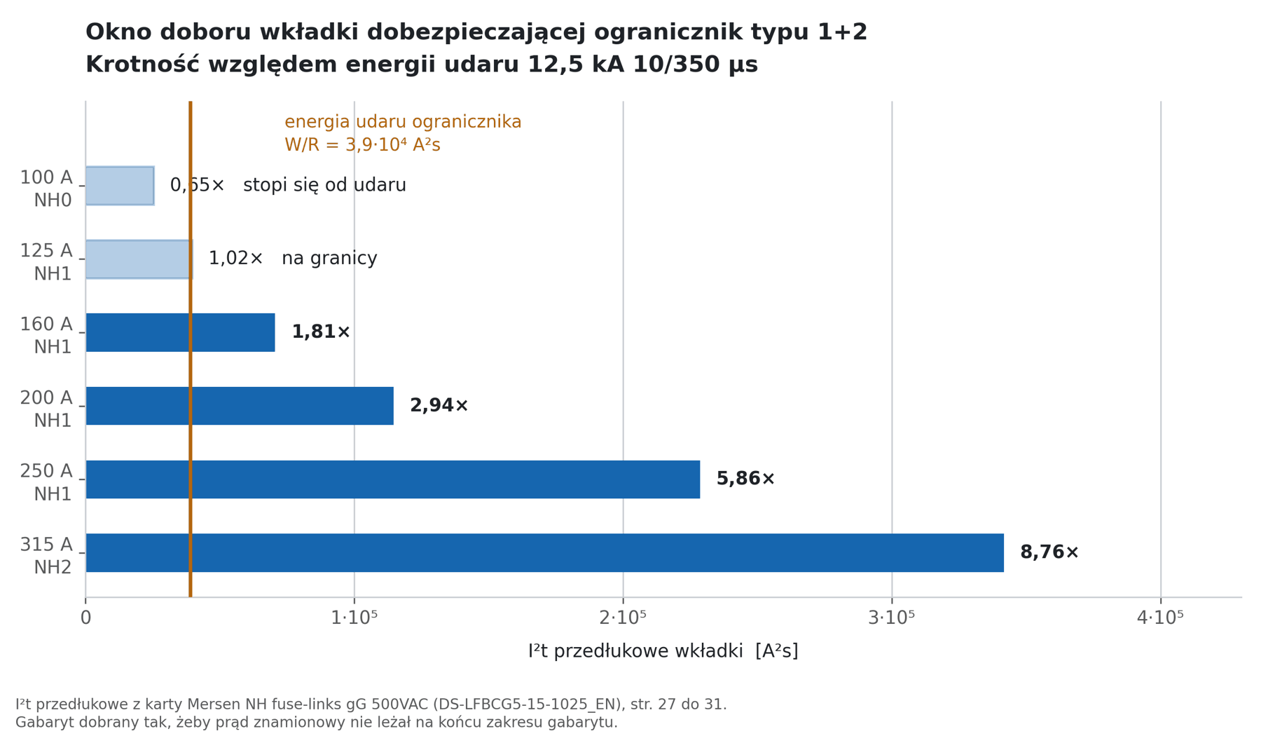
The fuse selection window runs from 160 to 315 A gG.
The lower boundary is set by the fuse datasheet values. A 500 V NH gG fuse rated at 100 A has a pre-arcing integral of 2.5 · 104 A²s, equal to 0.65 times the impulse energy – it will melt on the first strong discharge. A 125 A fuse gives 3.97 · 104 A²s, a ratio of 1.02 that leaves no margin for repetitive impulses. The practical lower threshold opens at 160 A at a ratio of 1.81.
The fuse rated current alone is not sufficient to verify impulse withstand. The pre-arcing integral also depends on the size class: a 315 A fuse in size NH1 has 1.85 · 105 A²s; the same rated current in size NH2 gives 3.42 · 105 A²s. The difference arises because 315 A sits at the top of the NH1 range but within the NH2 range. For a 315 A fuse, size NH2 is the correct choice.
The 160–315 A window applies for a single impulse. For repetitive impulses the fuse withstands without damage a lower Joule integral: 22 kA²s for 160 A, 39 kA²s for 200 A, 69 kA²s for 250 A6 – against 39 kA²s of impulse energy for 12.5 kA, the lower boundary shifts to 200–250 A. Hence the selection rule: the back-up fuse rated current equals the maximum fuse permitted by the SPD datasheet, i.e. 315 A gG for the K1 series. A smaller fuse does not increase the short-circuit withstand rating of the combination, and when subjected to an impulse several times its melting current it risks rupturing7.
For the same reason, a cylindrical fuse base on a DIN rail is unsuitable: gG fuses in that format are limited to 50 A in the 14 × 51 size and 125 A in the 22 × 58 size, both below the practical lower threshold.
A fuse in the supply circuit can also act as back-up protection, provided its rated current does not exceed the value stated in the SPD datasheet8. In the main switchboard of a substation from 1250 kVA upward, the rated LV current is 1.8 kA, so the supply-circuit fuses are many times larger than 315 A and that route is ruled out – back-up protection must be placed in the branch.
With the SSD holder installed, the external gG fuse in the SPD branch is no longer required. Both devices perform the same back-up protection function, and the manufacturer requires one or the other.
How Much Space Does the Combination Need and How Long Can the Conductors Be?
The SPD and SSD holder combination fits within 152 × 111 mm at a depth of 85 mm, and the total length of conductors from the branch point to the SPD and from the SPD to the PE busbar should not exceed 0.5 m. When retrofitting an existing switchboard, the available installation space is often limited to a single free section of rail. A 3-pole NH1 disconnector occupies 185 × 238 mm at a depth of 110.5 mm, and its cover requires 287 mm when open. The SSD combination mounts on TH35 rail without any cutout in the mounting plate.
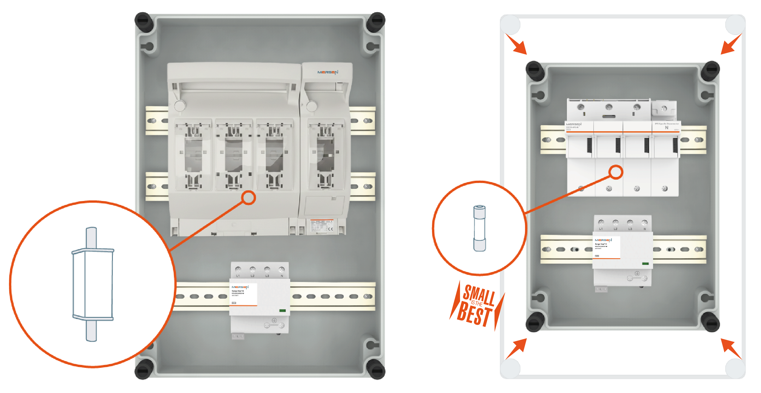
NH disconnector with SPD (left): four fuse base poles occupy the upper half of the enclosure. SSD holder with SPD (right): both devices on TH35 rails, enclosure two sizes smaller. Same enclosure, two approaches to back-up protection for the same SPD. Manufacturer’s photographs.
The voltage protection level must include the inductive voltage drop across the conductors from the branch point to the SPD and from the SPD to the PE busbar. For an 8/20 µs impulse at 20 kA and a conductor inductance of 1 µH/m, each metre adds 2.5 kV. A PV inverter in overvoltage category III withstands 4 kV, so the margin disappears at one metre of conductor.
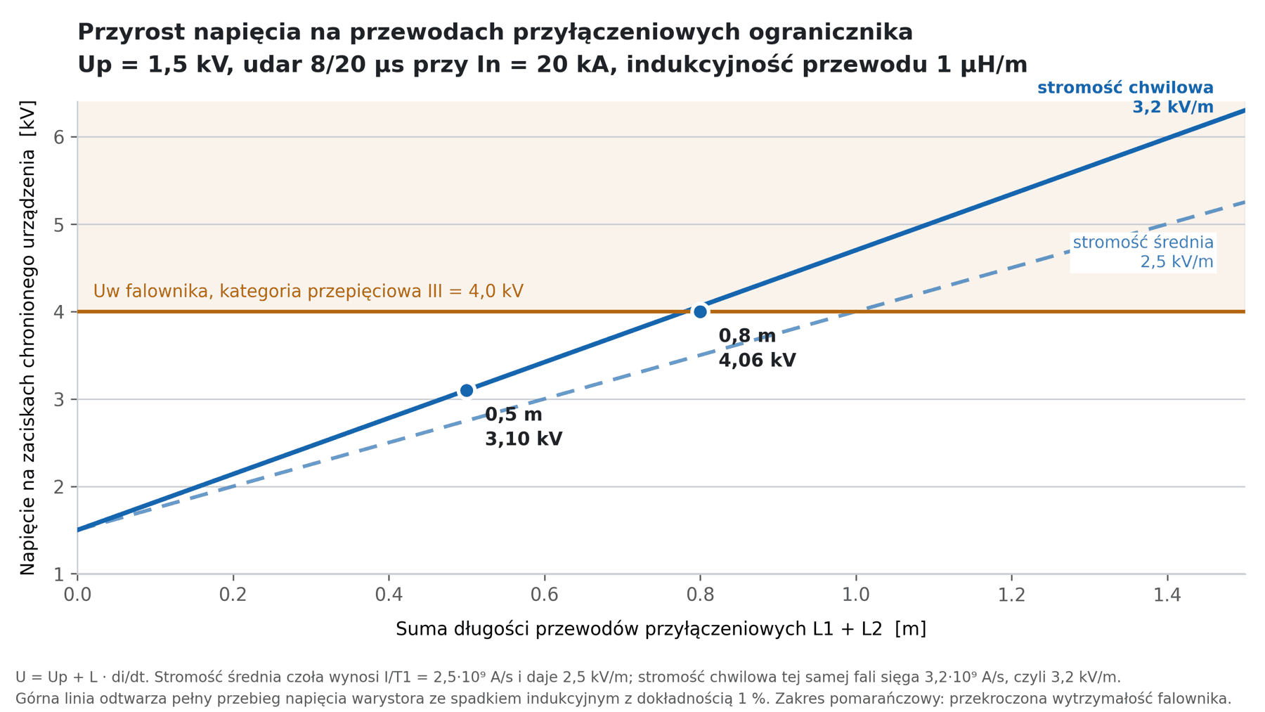
Voltage at the terminals of the protected device as a function of connecting conductor length. The value of 2.5 kV/m is based on the average rate of rise of the wave front; the instantaneous rate of rise is about one third higher and shifts the 4 kV crossover from one metre to 0.8 m.
At the instantaneous rate of rise, the margin disappears at 0.8 m. Hence the 0.5 m limit for both conductor sections combined and the installation of the SPD close to the N and PE busbars.
Common Questions When Replacing a gG Fuse with an SSD Holder
When replacing a gG fuse with an SSD holder, two questions recur: the cost of the second device, and the SPD built into the inverter. The answer to both follows from the figures in the preceding sections: from the fuse selection window, from the NH disconnector dimensions, and from the waveform to which a Type 2 SPD is tested.
We Already Have an NH Disconnector with a gG Fuse – Why Add a Second Device?
The price difference is smaller than intuition suggests. An NH1 disconnector with a full set of fuses costs around 15 % less than a 3-pole SSD holder. For a 315 A fuse – where the correct size class is NH2 – the disconnector-and-fuses combination costs the same or more and takes up considerably more space. An NH1 disconnector requires 185 × 238 mm of mounting plate; a 3-pole SSD holder occupies 80 mm of TH35 rail.
Above the short-circuit withstand rating stated in the SPD datasheet, a fuse does not solve the problem regardless of price: the selection window closes at 315 A gG at the top and at the impulse energy at the bottom.
The Inverter Has a Built-In AC-Side SPD – Is That Not Enough?
PV inverters frequently include a built-in Type 2 SPD on the AC side, and that stage can then be omitted. A Type 2 SPD is tested with an 8/20 µs impulse and cannot substitute for a first stage where a portion of the lightning current in the 10/350 µs waveform shape may enter the installation. It also protects its own installation point – the inverter terminals – not the incoming section of the main switchboard.
How Does This Work in Practice? Example: 300 kWp PV Installation
In practice the same SPD receives different back-up protection depending on the prospective current at the installation point. A 300 kWp rooftop PV installation on an industrial building, two 110 kW inverters, TN-S 230/400 V network. Power export to the main switchboard via a 350 m cable. Vertical air-termination rods on the roof without a maintained separation distance, requiring a Type 1 SPD on the AC side.
Protection is needed at both ends of that cable: at the building and in the main switchboard. The prospective short-circuit current calculated separately for each point determines the back-up protection selection.
| Connection point | Short-circuit current | Back-up protection |
|---|---|---|
| Cable connection at the building | approx. 15 kA | gG fuse or SSD holder |
| Main switchboard section | 38 to 75 kA | SSD holder only |
The same SPD serves both points; what differs is the back-up protection. At the building enclosure the choice was settled by space: the free section of TH35 rail in the switchboard was just under 180 mm – exactly right for a Type 1+2 SPD and a 3-pole SSD holder.
What to Check When Specifying Surge Protection?
When specifying surge protection, check seven things: four relate to the datasheet and the short-circuit current, three to the installation point. The order matters, because without the prospective current at the installation point it is impossible to determine whether a gG fuse is sufficient.
- Read two values together from the SPD datasheet: the short-circuit withstand rating and the maximum upstream fuse.
- Establish what the declared withstand rating refers to: the combination with back-up protection or the SPD alone, and whether the value is rms or peak.
- Calculate the prospective short-circuit current at the SPD installation point, separately for each connection point.
- Compare the pre-arcing I²t of the fuse with the specific energy of the SPD at its rated impulse current; first check which of the two quantities the datasheet states – the method for doing so is described in the section on reading declarations.
- Measure the installation space: width, height, depth, and conductor routing clearance.
- Plan the PE busbar conductor route before selecting the mounting position, with the 0.5 m limit covering both conductor sections including the branch.
- If the prospective short-circuit current exceeds the declared withstand rating of the combination, use an SPD-specific disconnector tested with that SPD series.
Select the Right Back-Up Protection with ELTRON
The short-circuit withstand rating of a surge protective device is a property of the combination with its back-up protection, not of the SPD alone. With a gG fuse selected from the datasheet table, the combination is limited to 25 kA – sufficient up to approximately 1000 kVA. Above that transformer rating the busbar current rises to 75 kA, requiring the SSD holder, which is tested together with a specific SPD series to 100 kA. The combination occupies 152 mm of TH35 rail, and the choice between the 12.5 kA and 25 kA versions is determined by the lightning protection level of the installation.
ELTRON supplies SSD K1 and K1H holders together with Surge-Trap® K SPDs and assists with back-up protection selection based on the prospective short-circuit current at the specific installation point. If you have a switchboard project or a retrofit of an existing enclosure, contact us – we will calculate the prospective current and match the combination to the available rail section.
Author: Damian Zazula – Product Manager, ELTRON (Mersen, Sensata, Joslyn Clark)
Sources
Product data: Mersen datasheets DS-SSD-K1-Series-EN, DS-SSD-K1H-Series-EN, DS-Surge-Trap-K-K1-EN, DS-Surge-Trap-K-K1H-LF-Series-EN; Mersen catalogue “Surge Protection Devices 2026”; brochure “Surge-Trap IEC Lightning & Surge Protection” (Mersen); Mersen France SB declarations for Surge-Trap® K1 + SSD K1 and K1H LF + SSD K1H systems tested at 100 kA at the LRIC laboratory, Terrassa, 9 April 2026; DEKRA certificates for Surge-Trap® K1 (71-150224) and K1 LF (71-150235). NH gG fuses: Mersen datasheet DS-NH-fuse-links-gG-500VAC.
Standards and documents: IEC 62305-1 (lightning current parameters for LPL protection levels); IEC 60909-0 (short-circuit current calculations); EN 61643-11:2012/A11:2018 (test basis in the DEKRA certificate); TAURON Distribution Technical Standard 5/2014 and Energa-Operator specification ST-Z02 (distribution transformer parameters).
References
1 Musiał E., Back-up protection of surge protective devices, SEP INPE Bulletin “Information on Electrical Standards and Regulations” 2006, No. 76–77, pp. 3–37, Table 2 (impulse operating currents of gG fuses).
2 Musiał E., ibid., Ch. 3 “Relative positioning of arresters and fuses”.
3 Musiał E., ibid., Ch. 8 “Surge protective devices in the installation and shock protection”, Fig. 14.
4 Musiał E., ibid., Ch. 4 “Distribution of lightning current”, formula Iz = ν·IG/m; current distribution factor ν = 0.5 per PN-IEC 61312-1:2001, justified range 0.35–0.65.
5 Musiał E., ibid., Ch. 2 “Surge arresters – Class I SPDs” and Ch. 6 “Follow-current-limiting surge arresters”.
6 Musiał E., ibid., Table 3 (Joule integral of lightning current repeatedly carried by gG fuses).
7 Musiał E., ibid., Ch. 3 and 5 (fuse rated current equal to the maximum permitted; Fig. 6 – behaviour of gG fuses under lightning current).
8 Musiał E., ibid., Ch. 3, Fig. 1c (supply-circuit fuse as back-up protection).